Construct this simple hoist and easily rack and unrack that old PDP-11 without racking your back!
Introduction
I’m sure you are aware that old DEC PDP-11 minicomputers and peripherals are heavy bastards. Lifting one without support when racking an old Unibus CPU, RK05 or tape unit could seriously hurt your back if you’re not careful, as well as potentially damage your precious gear. The PDP-Lifter described here should hopefully reduce the chance of a back injury as well as be able to finely adjust the height of the equipment up or down and in and out to allow the rack slide screws to be located level with the device.
 |  |
In addition the PDP-Lifter can do this both outside the rack or be wheeled under and partially or completely into the rack (eg. a DEC H960) allowing a non-rackslide fixed device (ie. on a shelf) to be installed or removed, provided a 1RU gap is available to slide the platform in. The PDP-Lifter came into existence after some discussion on the cctalk mailinglist about how to lift heavy and fragile gear to and from 19″ racks. Some suggestions of a scissor-lift trolley jack were given, however the expense of that particular unit itself and the subsequent cost of importation from the US to Australia would have been prohibitive. And even then it was quite large and would have been unable to roll underneath and into the H960 rack anyway. Other people have used slings and engine lifting gantries, but I felt what was needed was a more bespoke solution.
Looking around my garage I realised I already had a fair amount of odds and ends to build a simple, light duty lifter without spending a lot of money. Its capacity is restricted to around 70kg maximum and has been successfully tested to that limit with a stack of house bricks. My FOX 2 CPU weighs in at around 39kg so this is well within the lifting range of the device.
You can build a PDP-Lifter yourself. Hopefully the following photos, description and Bill Of Materials will be enough to get you going. By no means is the device critical in any dimension apart from the need to keep the top of the caster legs lower than the bottom of the H960, and that the platform width must be narrow enough to accommodate being lifted up and down clear between any rack slides already fixed in place that impinge upon the inner of the equipment rack. Apart from that, the rest will depend on what you find in your location.
Usage
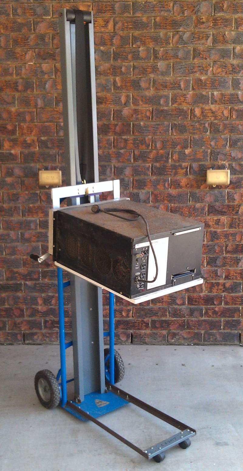
Here are some photos of the PDP-Lifter being used to lift, transport, adjust finely up and down my FOXBORO FOX 2 computer, a rebadged PDP-11/15. The PDP-11/15 is mostly similar to the PDP-11/20 except it has a 16-bit address switch register and KC11 CPU instead of the /20’s 18-bit switch register and KA11 CPU module set.
This particular computer ran process control for fire prevention in the Furnace Oxygenation Plant at the BHP steelworks, Port Kembla, Australia from its installation in 1974 to its decommissioning sometime late in that decade. As such it has some provenance in Australian computing history. It was saved from being scrapped when I went on an interstate road trip to recover it in early 2016. As I was not permitted to have the original PDP-11/20-style rack slides when recovering the equipment, and cost of importation of some pairs of original Chassis-Trak units from the USA was going to be on the order of $500 postage alone, I modified a salvaged pair of modern server rack slides to suit.
The rack was originally a 12RU solid-walled cabinet for holding TV station equipment that I split into two and rewelded the back verticals above the fronts, doubling the height. The sides and top panel were cut out and a mesh fitted to the top to stop things falling in.. The replaced back verticals of the rack are pieces of angle iron salvaged from an old bed frame, drilled with RU-spaced holes.
The interconnect panel behind the paper tape reader is the FOXBORO DBI bus, which is essentially a breakout board from a double-wide Unibus cable from the PDP-11 to a series of Winchester MRAC connectors. I managed to save some of the cables for this.
Construction
Right, let’s get started. Please note that the photos have been rearranged a little bit from the order in which they were originally taken to show a more logical sequence of construction steps.
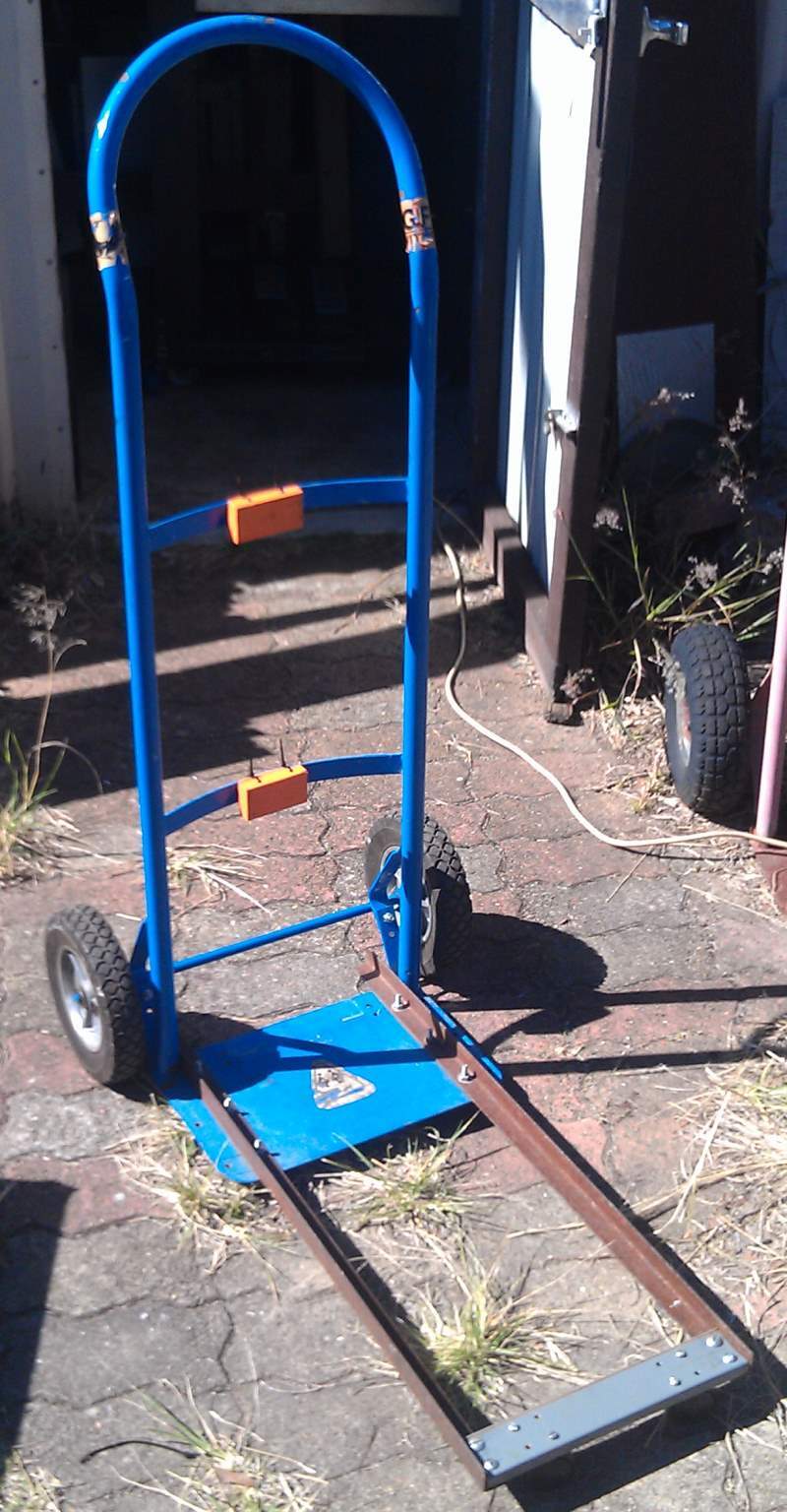
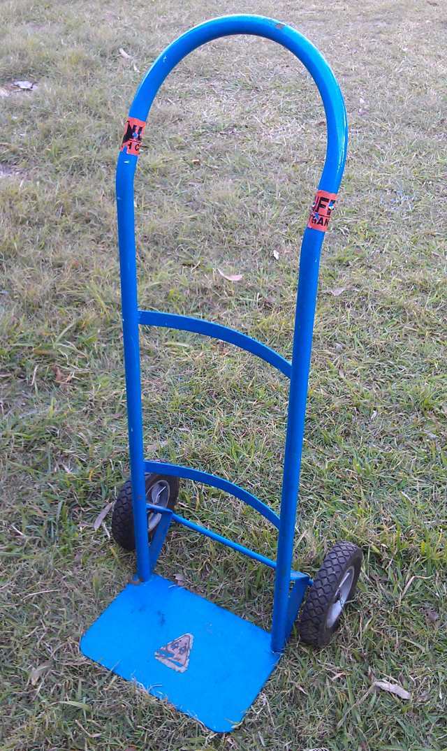 | Obtain a small hand cart (item #1), as used for moving boxes or garden supplies. I also had another cart with larger pneumatic tyres I could have used, but this unit with smaller 200mm dia solid plastic and rubber wheels seemed more suitable for the job in that the smaller wheels would allow it to roll up a bit closer to the rack. And as a bonus they would not need to be pumped up. I have had this one lying around for many years but they are quite inexpensive. Stick to the one-piece all-steel welded variety and not a foldable aluminium job. |
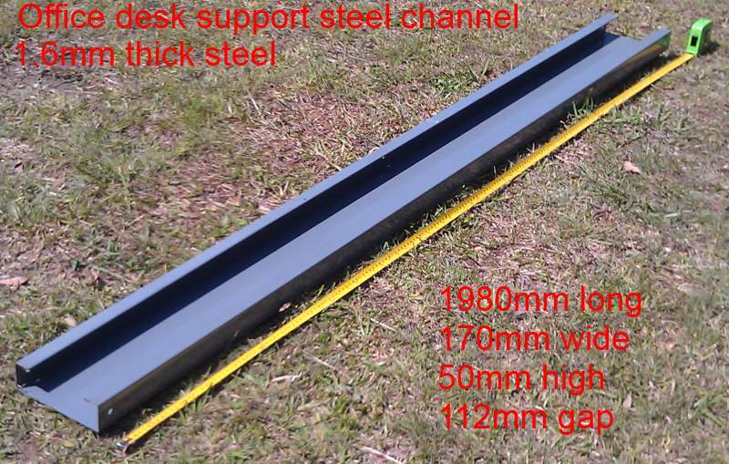 | Item #2, the vertical channel, just short of 2m long. This steel C-box section item is from a modern office desk that was being scrapped. Full dimensions are described in the BOM. If you cannot find something similar you may be able to use two ~2m long x 50mm x 100mm (2″ x 4″) pieces of smooth straight hardwood lumber, spaced accordingly with cross pieces of lumber across the top, middle and bottom. Or alternatively two pieces of 50mm square steel rectangular hollow section (RHS). Small standoff spacers would be needed to allow the lifting platform slide part to move up and down unimpeded. |
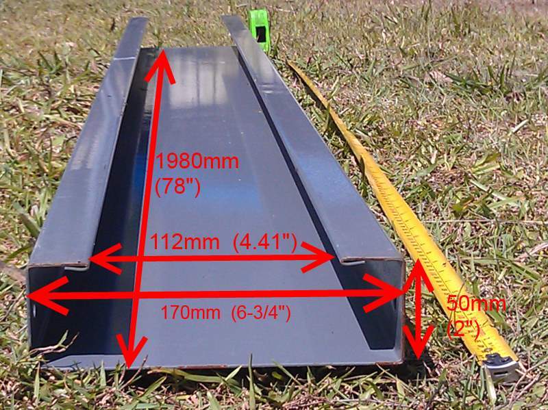 | End of the channel showing the cross-section. The channel is folded 1.6mm mild steel, powder coated, with the two edges folded inside the gap. The only holes in the channel are along the sides close to the ends and a couple of small holes in the back. |
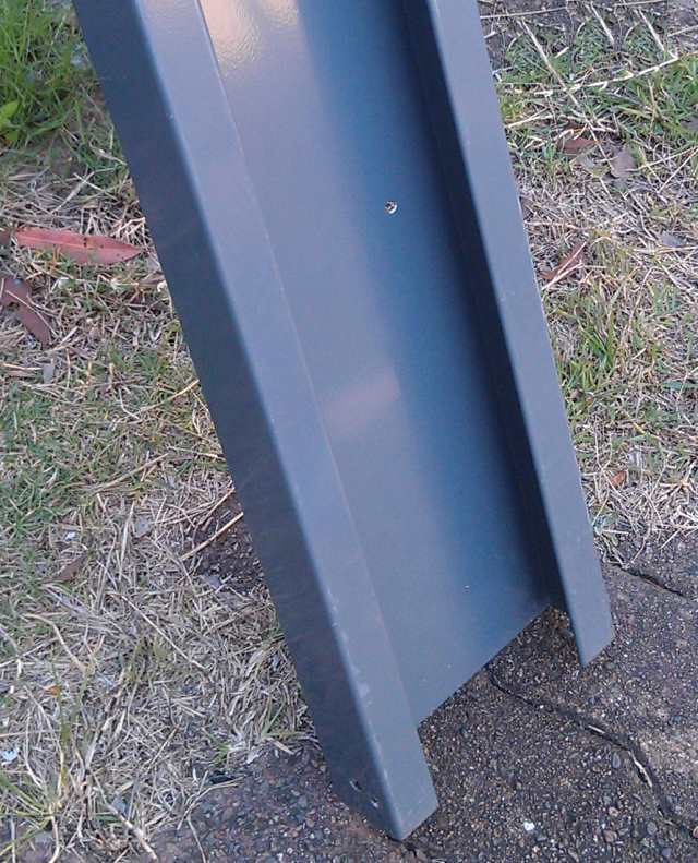 | Another view of the end of the channel. |
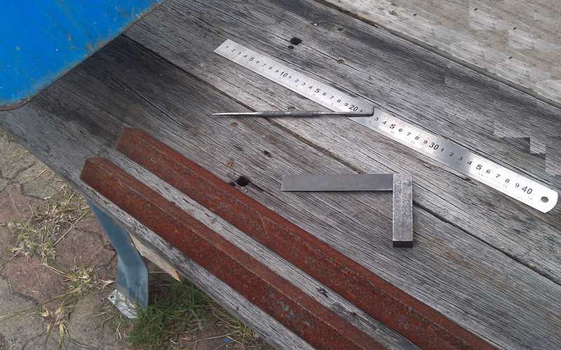 | Starting to mark out the two 740mm lengths of 25mm x 25mm x 3mm angle iron (item #4) for the baseplate caster legs. |
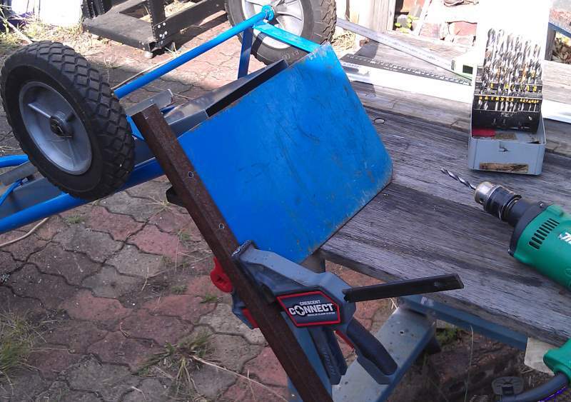 | This was the initial position I placed the angle iron on, underneath along the edges of the trolley baseplate. HOWEVER… I forgot to allow for the H960 floor gap width, so the channels were moved from here to the top of the baseplate and just touching the inside of where the trolley handle tubing was welded on. The holes for the angle iron in through the bottom of the baseplate are countersunk for the 1/4″-20 screws (item# 25) with the nuts securing from the top inside of the angle iron. You can see the final proper placement in the following two photos. |
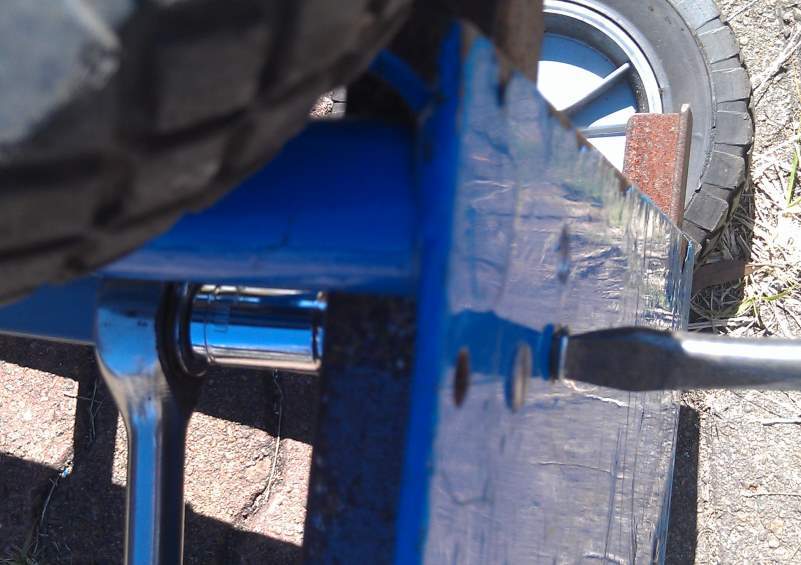
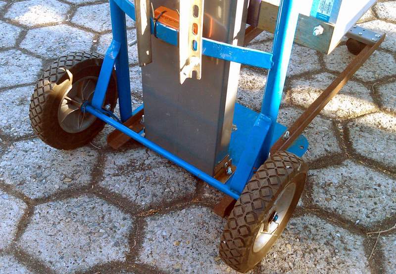
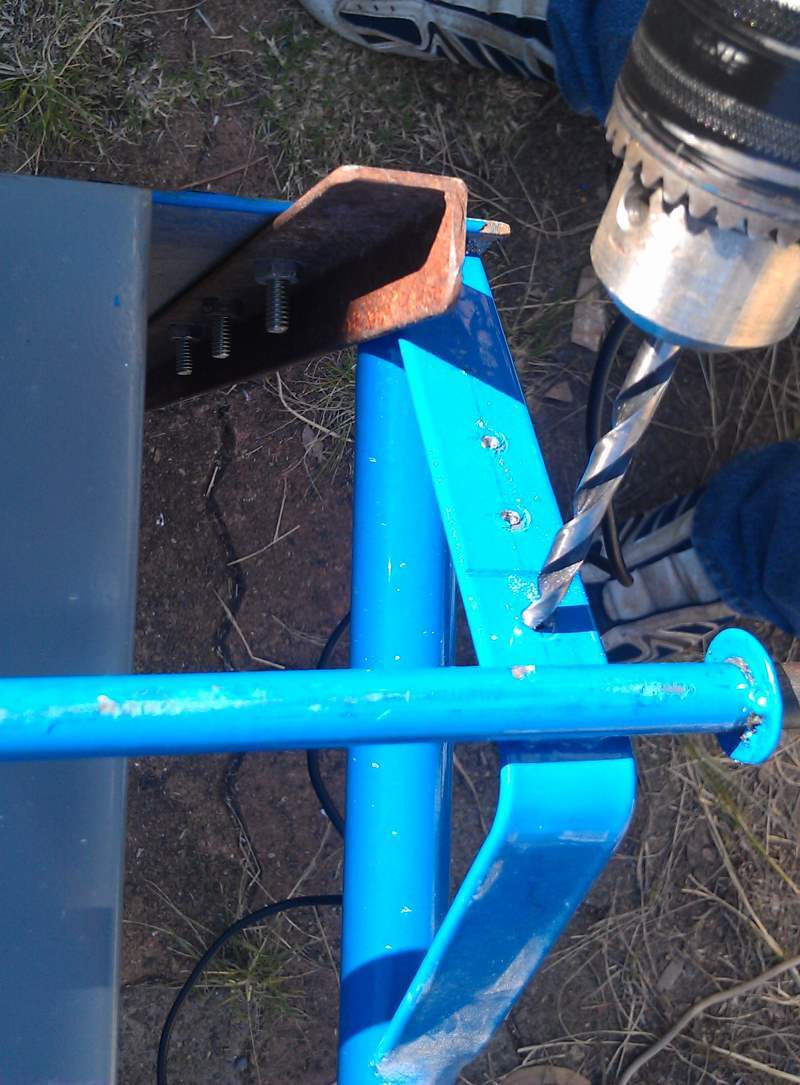 | As it stands vertically, unobstructed, the bottom of the trolley baseplate touches the ground with the wheels slightly in the air, as designed, and the wheels only make ground contact when pulled backwards by 20 degrees or so. Since the trolley must be wheelable at all times, the wheels are lowered so there is a 15mm or so gap between the ground and the bottom of the baseplate. This is done by drilling a few evenly-spaced 1/4″ holes in the lower wheel brackets about 25mm apart. You need a minimum of two holes, I drilled 3 in case I did not have enough ground clearance and needed to bend it more. As it turned out, the spacing of about 30mm was perfectly adequate. |
 | After the holes are drilled, use a hacksaw to cut the bracket through (do not cut first then drill). Then with a hammer or rubber mallet, tap the upper side of the bracket near the axle shaft (alternately tapping on both left and right wheel brackets to reduce twisting) so it swings and bends down enough to put a 1/4-20 screw (item #27) through with a nyloc nut. Tighten securely. |
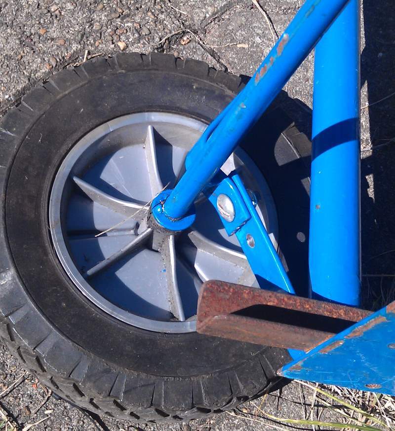 | Detail showing the adjusted bracket, which now gives the trolley baseplate bottom about 15mm (3/4″) permanent ground clearance at all times. |
 | The front caster bar has been completed. I used a scrap of another channel, but in the BOM I suggest instead to use a piece of steel bar (item# 5) with spacers (item# 7) stacked inside the angle iron to bring the top of the bar closer to the top edge of the angle iron, affixed with screws (item #25). The casters (item# 6) are the absolute maximum size that can be used and still slip under the H960, perhaps four casters of a slightly smaller diameter spaced out along the bar would be better. |
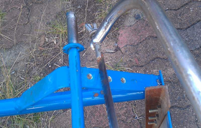
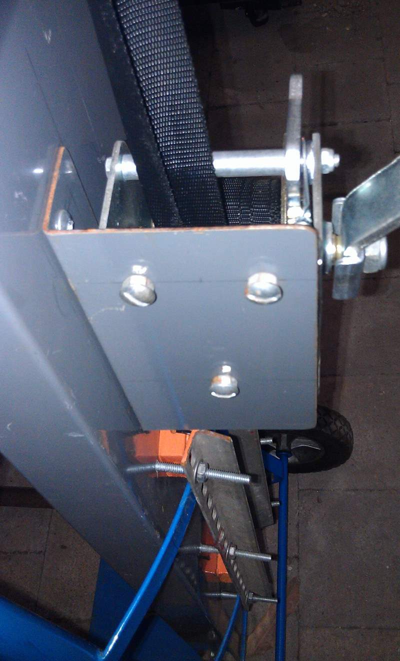
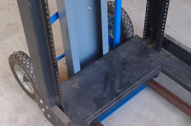
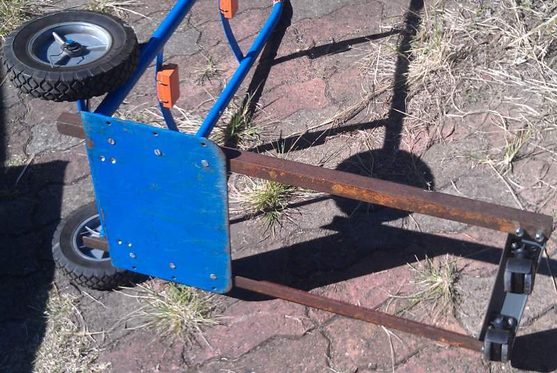 | Underside showing the arrangement of the front caster bar. In addition the painted orange blocks are wooden spacers (item# 11) which touch the back of the vertical channel. They are fixed in place onto the handle cross braces with some plastic cable ties, with the curved surface facing the brace. The two pairs of countersunk holes toward the rear edge of the baseplate are for two angle iron brackets (items# 4 and 10) which secure the bottom edge of the channel to the baseplate and stop it being pushed out of shape and backwards when weight is applied to the platform. |
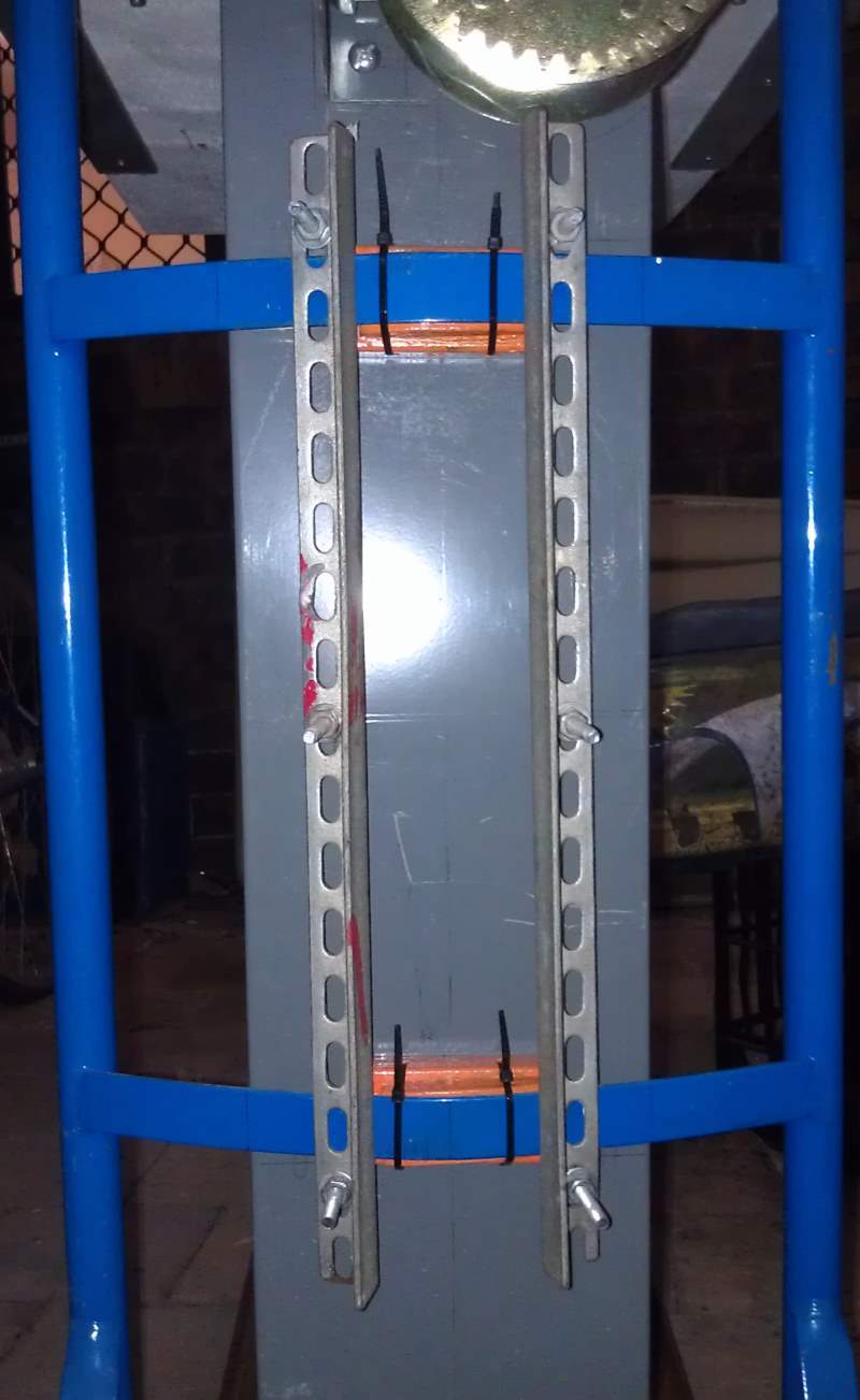 | The two vertical pieces of angle iron (item# 9) securing the channel to the trolley via the handle’s cross braces. The two wooden spacer blocks (item# 11) have one curved surface that buts against the cross braces. |
 | Using a screwdriver and ratchet socket wrench to tighten the countersunk 1/4-20 screws (item #25) that affix the angle iron brackets (item# 10) that hold the bottom edge of the channel to the top of the trolley baseplate. The other short screws (item# 27) go through these brackets into the sides of the channel. |
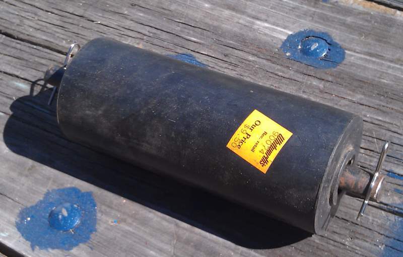 | The solid rubber trailer roller (item# 13), from a boating supplies shop, originally bought for another purpose but never used. Through this goes a steel axle (item# 14) salvaged from an old printer or photocopier and secured inside the top of the channel with a Presto-pin (item# 15) through a 3mm hole drilled through each end of the shaft. |
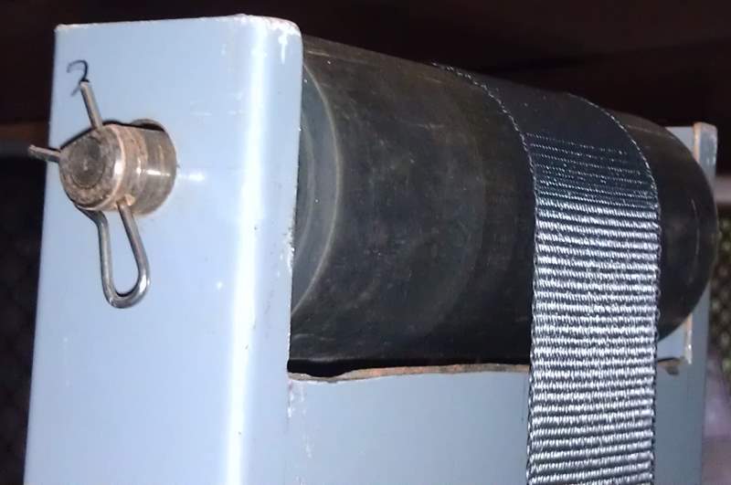 | A view of the back of the channel with the roller in place. A recess was cut in the top of the channel so that the roller periphery would be clear of the back side of the channel, down to the winch, and that the webbing path would therefore be unimpeded from the winch over the roller down to the platform. |
 | The winch mounting bracket (item# 8). I cut an angle piece of steel from another identical channel for this, but any arrangement to make the winch handle rotate parallel to the rear surface of the channel would do. |
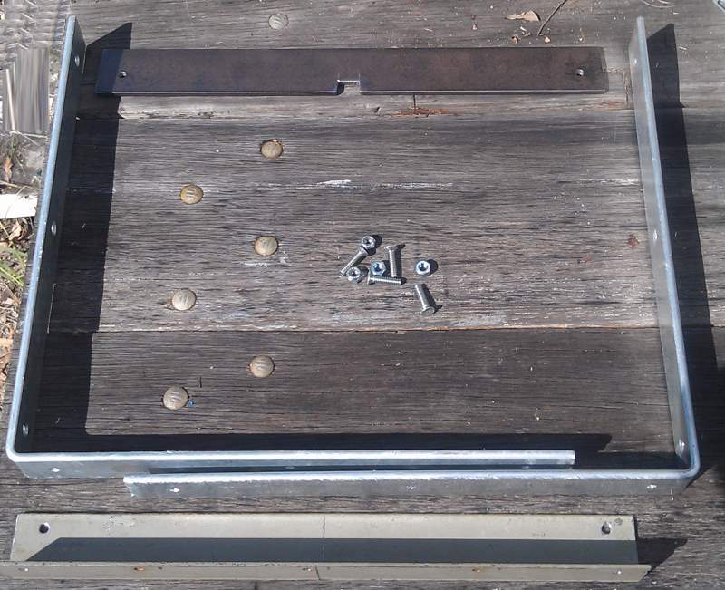 | Constructing the moveable lifting platform. Two galvanised shelf brackets (item# 16) measuring 380mm on a side are secured with 1/4-20 screws (item #27) to two pieces of metal. The bar at the top (item# 17) has a recessed notch made with a hacksaw to keep the winch hook from sliding to one side or the other. The bottom piece of angle iron (item# 18) is affixed on the outside of the bracket corners with 1/4-20 screws (item# 27). |
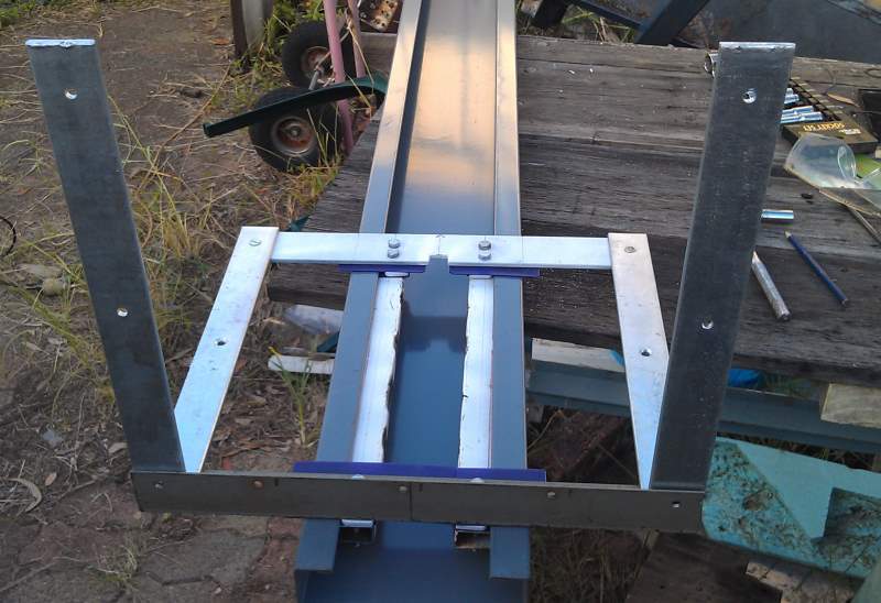
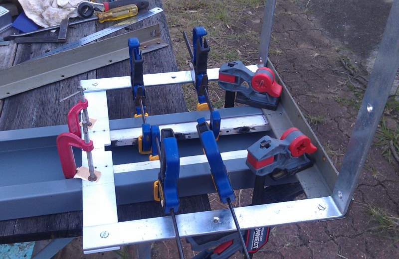 | After the brackets are arranged with the top and bottom pieces, the next step is marking out for drilling the inner steel pieces that hold the platform within the channel. I had a scrap of RHS (rectangular hollow section) steel that I cut in two (item# 21), clamped inside the channel (with a few mm spacing) and then drilled through. |
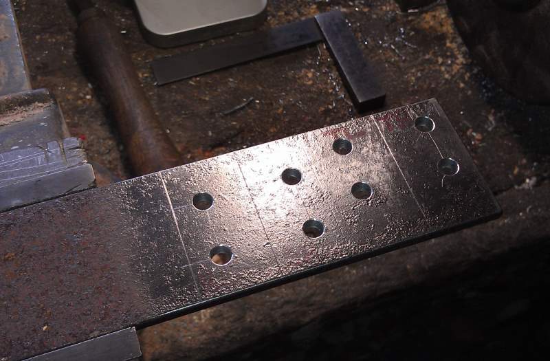 | Drilling a piece of 50mm wide x 5mm thick steel bar stock for the platform channel spacers (item# 22) prior to hacksawing into four separate pieces. |
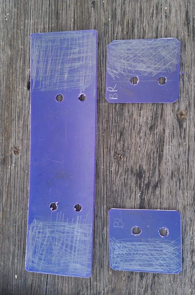 | To aid smooth movement of the platform within the channel, I cut some pieces of HDPE (or could be LDPE) plastic sheet for bearing surfaces (item# 23 and 24) sandwiched between the platform structure and the channel by screws. I scribbled on the plastic with a soft 6B lead pencil to give a little more lubrication. |
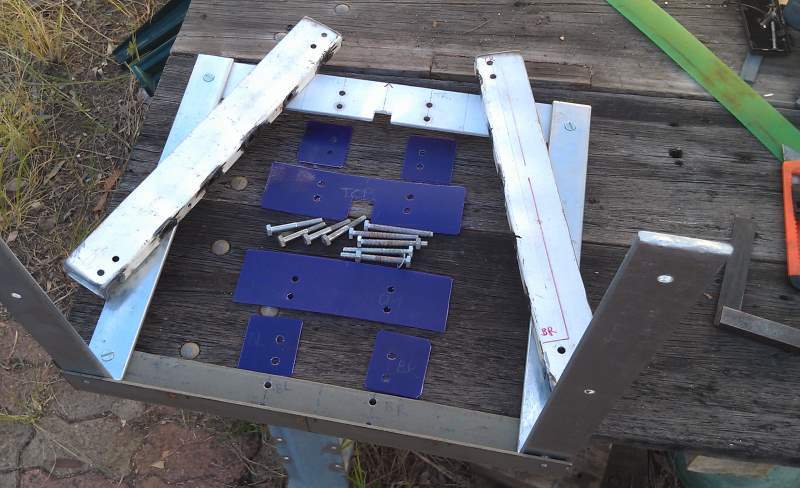 | Another view of most of the pieces of the platform before the slide assembly. The spacers are not shown in this photo. |
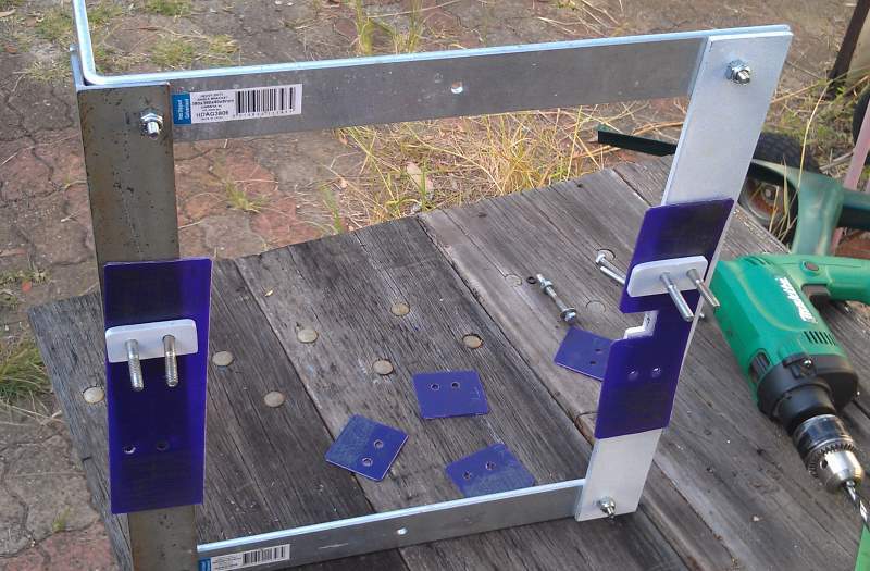 | Starting to assemble the plastic bearing sheets and spacers. |
 | Closeup of the spacer sandwiched with plastic sheet. The white painted piece with the holes drilled in (item# 21) is the inner retainer. |
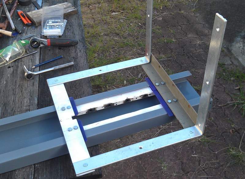 | Mostly completed platform, only lacking the plywood platform (item# 20) and top metal strip (item# 19). It slides freely along the length of the channel. |
 | Another view of the platform assembly, this time from the bottom, prior to the plywood being screwed on. |
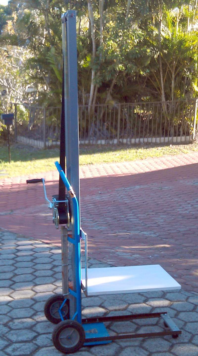 | The completed PDP-Lifter. At the time this photo was taken, the extra retaining strip (item# 19) on top of the plywood had not been added. It was only determined later that this strip would be beneficial for extra security in stopping the plywood being wrenched upward and off the woodscrews by a lot of weight forward of the end of the large brackets. |
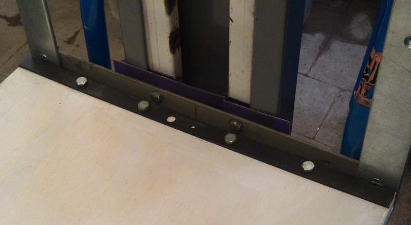 | The retaining strip (item# 19) in place. This is bolted right through the strip, plywood (item# 20) and lower angle iron (item# 18) to prevent the woodscrews ripping out of the plywood due to the extreme weight of the computer’s power supply towards the outer end of the platform. |
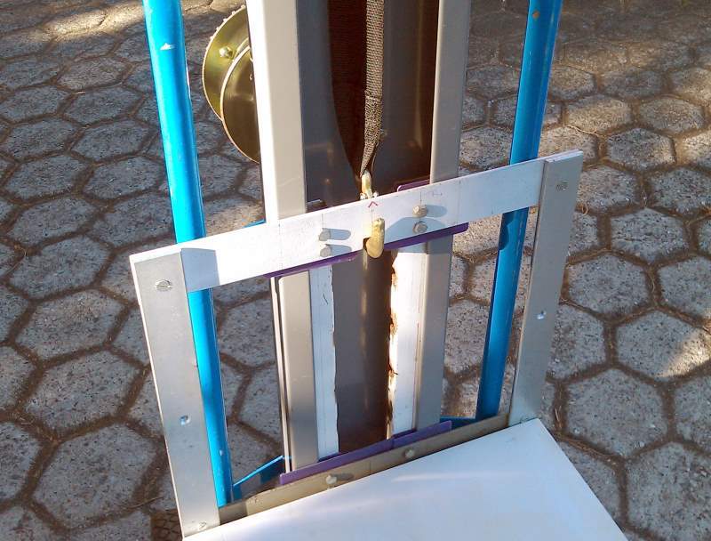 | Detail of winch hook in locating recess of top bar (item# 17). |
 | A view of the back showing the short pieces of angle iron (item# 10) for affixing the outer sides of the channel to the baseplate. |
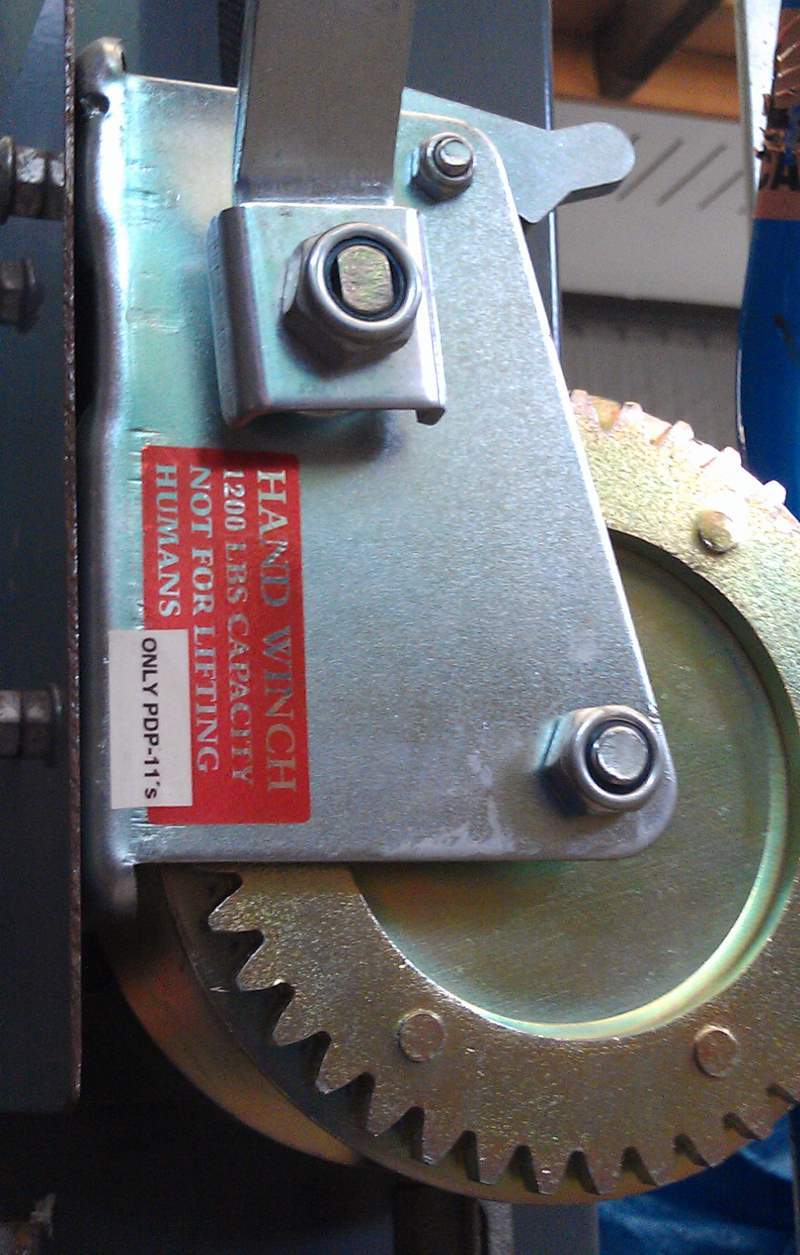 | Label on the winch. |
Testing
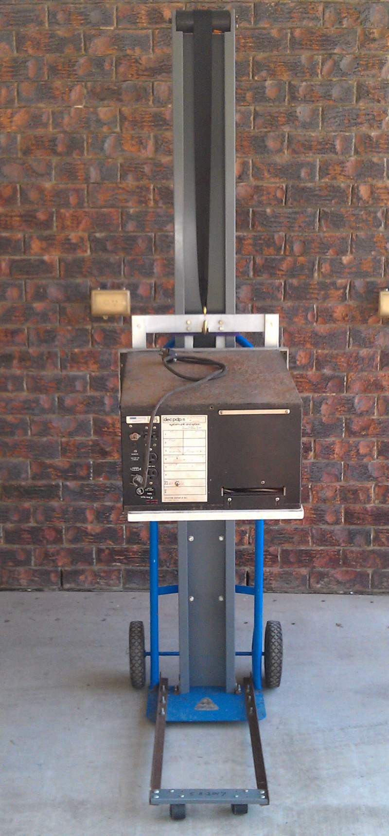
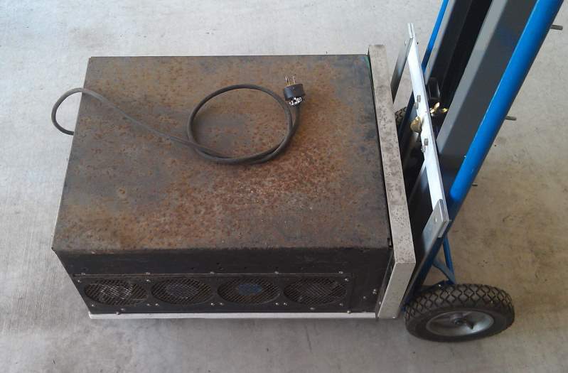 | The FOX 2, weight approximately 39kg (86 lbs), at the bottom of the trolley and ready for wheeling about. Note the plywood platform is slightly narrower than the width of the computer itself. |
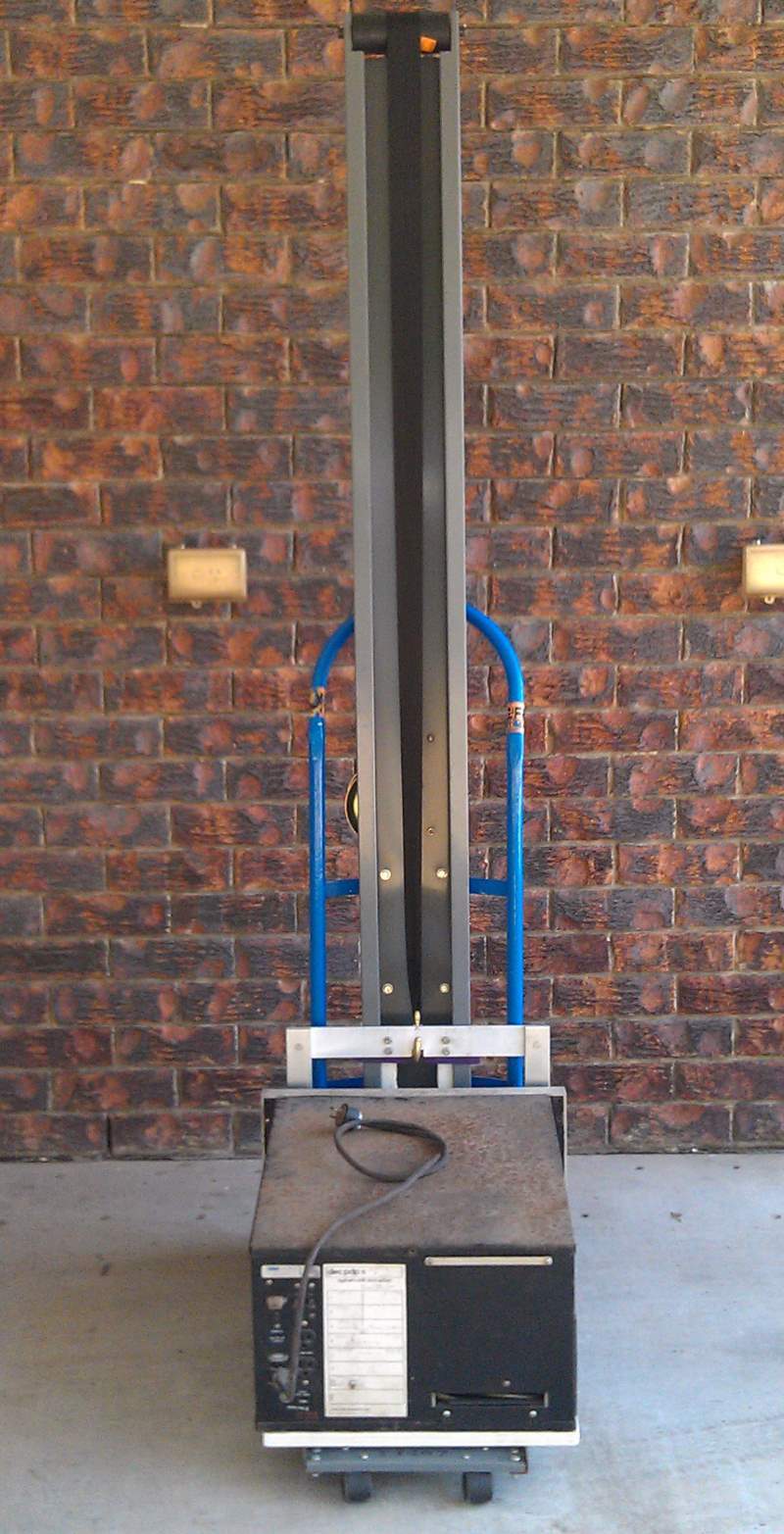
 | Back of the PDP-Lifter with computer at ground level. |
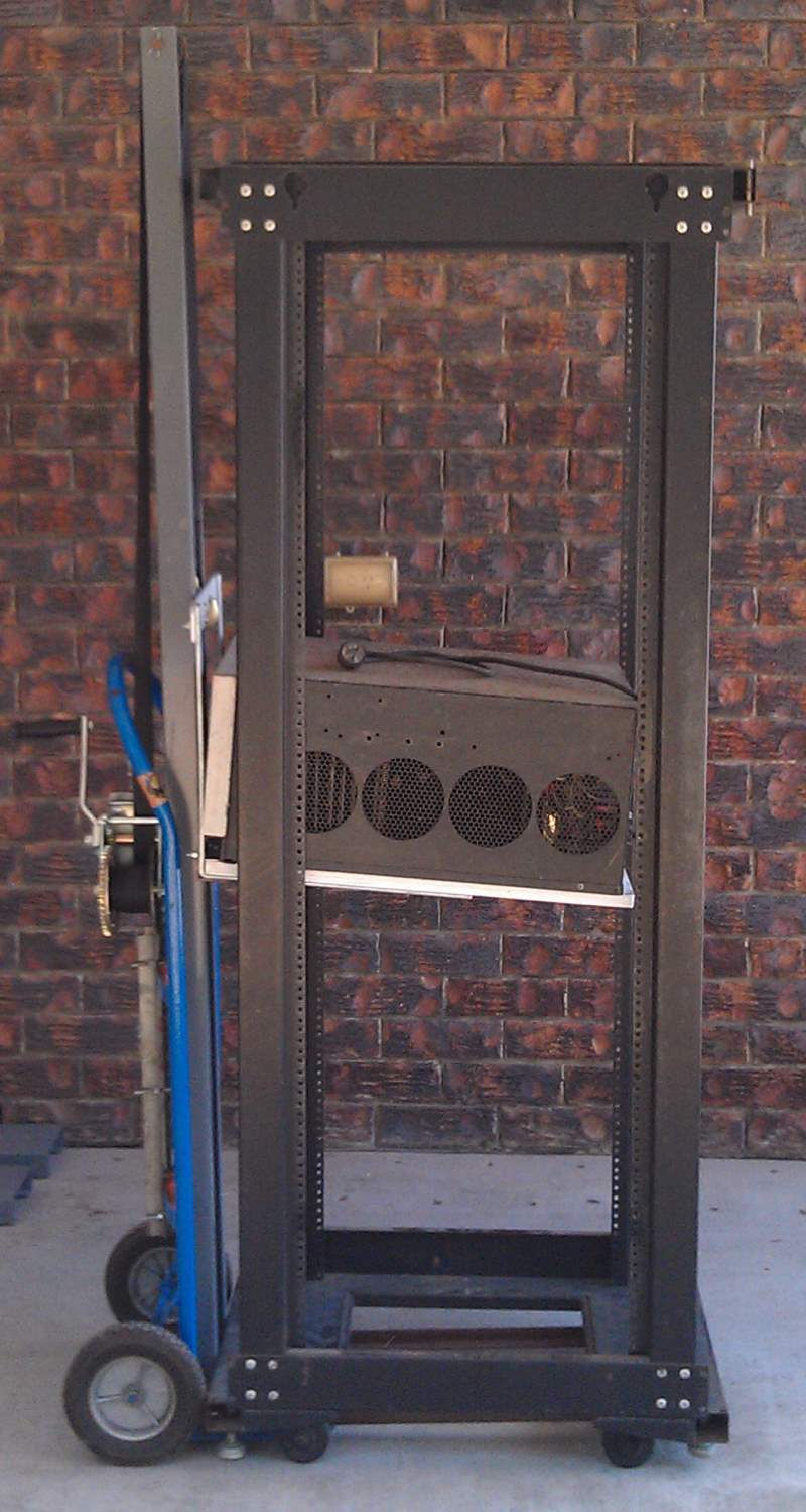
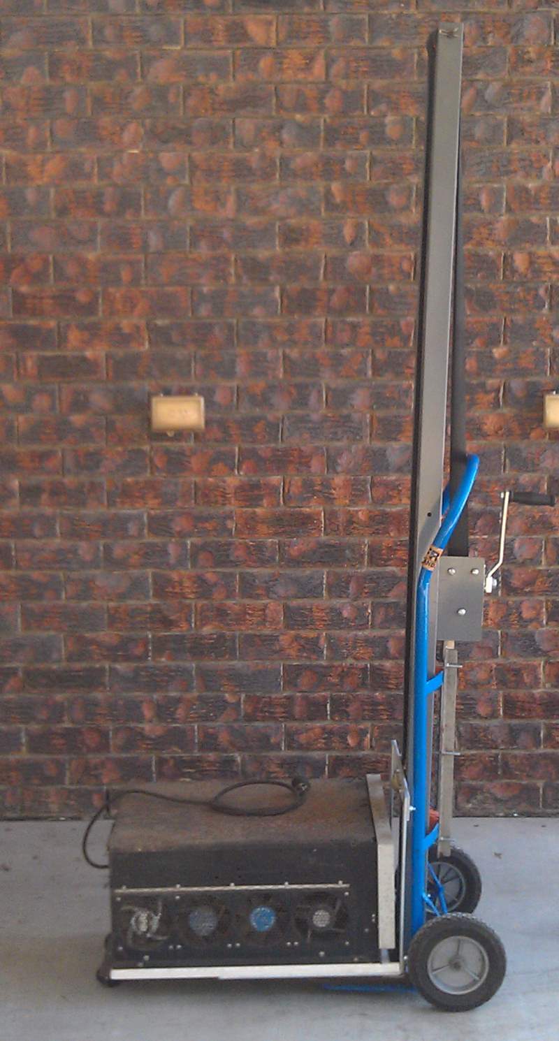 | Side view. |
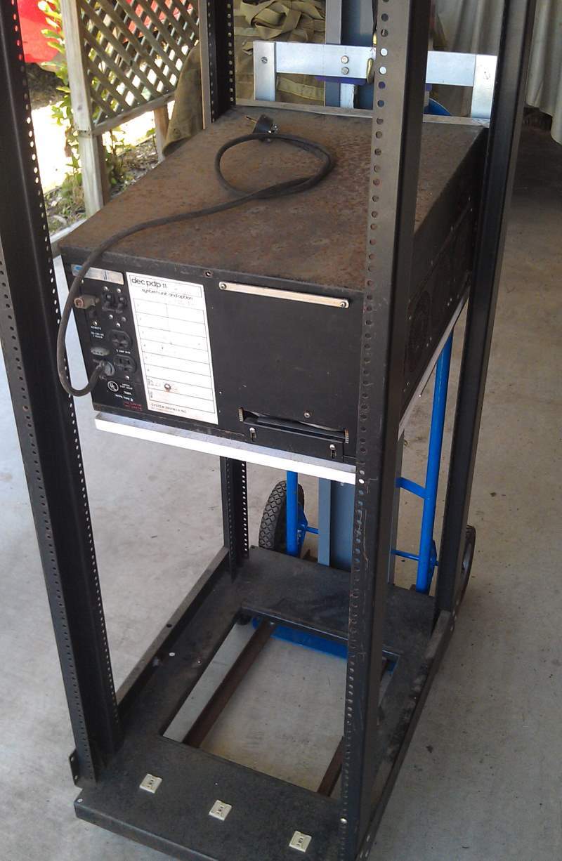
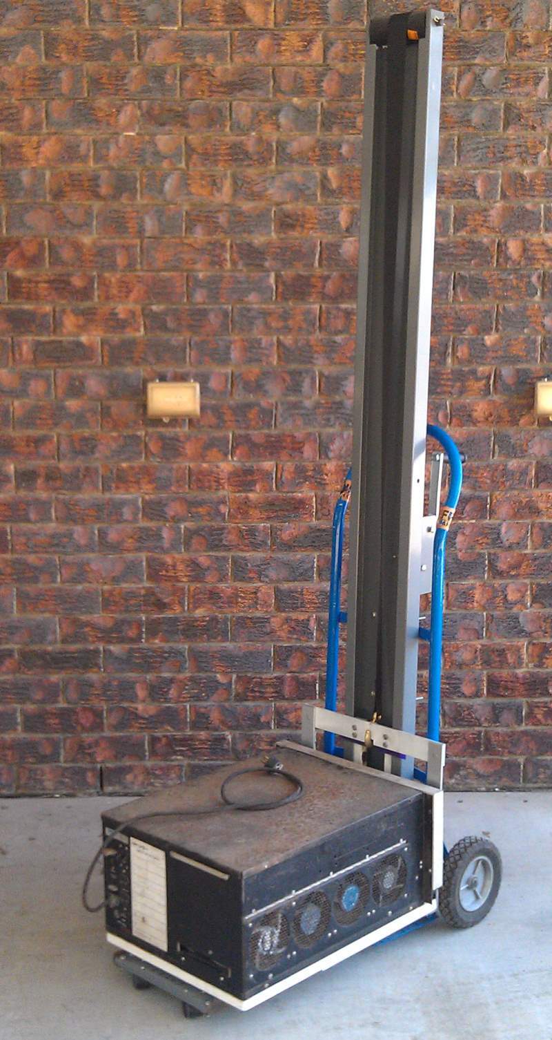 | Three-quarter view showing the back of the computer. |
 | Another view. |
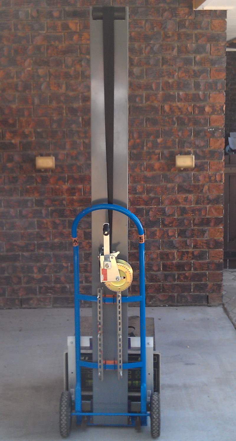
 | We have liftoff! |
| Hasn’t crashed back to the concrete yet, so all good. |
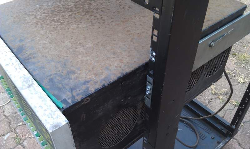
 | Test positioning the computer inside an H960 rack. This is not the rack this computer will be going in. Notice the slight angle leaning down, there is a lot of weight on those two brackets. Ideally a third or even fourth furniture bracket located inside the other two would take some more of the weight and level it out, but I’ve had no problems with it. It’s a tight fit for the caster legs under the rack, four smaller casters would probably be better. |
 | The channel is right up to the front of the H960 rack in this photo. |
 | How it looks, closer up. |
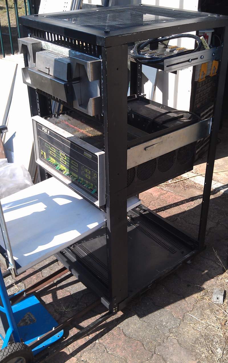 | The PDP-Lifter being removed after initial racking of the FOX 2 in a smaller rack. After this I used the device to move the computer up a further 2 RU height, which was now a trivial and quick operation. Notice the rack’s homemade support legs, which can be extended out about 500mm or so, and afterwards completely retracted under the rack. The paper tape reader is the same Digitronics unit installed with the FOX 2 in its original FOXBORO cabinet at BHP, which was enormous. |
 | The computer on modified modern server rack slides. It can pivot up 90 degrees as per the original setup. Next to be racked directly underneath the FOX 2 will be the DEC ME-11L memory expansion unit in the H-909 chassis (same as the PDP-11/05 slimline cabinet) then a BA-11K expansion box with some DD-11 modules, this provided the interconnection between the PDP-11/15 and the ME-11L. These were the original boxes connected to the computer as installed at BHP Port Kembla during the 1970s. I just need to finish some more modern server rack slide conversions then I’ll get to it. |
Bill Of Materials
| Item# | Qty | Description |
| Trolley and frame | ||
| 1 | 1 | Hand cart, 200mm (8″) dia solid plastic and rubber wheels |
| 2 | 1 | Office desk channel, C-profile, 1.6mm thick mild steel, powder coated, 1980mm long x 170mm wide x 50mm high with 112mm channel gap (78″ x 6-3/4″ x 2″, 4.41″ gap) |
| 3 | 1 | Hand winch, 545kg (1200 lb) capacity with nylon belt webbing and hook |
| 4 | 2 | Angle iron, for baseplate caster legs, 740mm long x 25mm x 25mm x 3mm thick (29″ x 1″ x 1″ x 1/8″) |
| 5 | 1 | Metal bar, for front caster support 288mm x 50mm x 5mm (11-3/8″ x 2″ x 1/4″ thick) |
| 6 | 2 | Caster, furniture, plastic 40m dia (1-1/2″ dia) with flat square plate fixture |
| 7 | 6 | Spacer, for caster support bar to angle iron base, steel plate or bar, 50mm x 20mm x 5mm thick (2″ x 3/4″ x 1/4″ thick) |
| 8 | 1 | Bracket, steel, 1.6mm thick to affix winch at right angle to channel 180mm x 100mm x 45mm (7-1/4″ x 4″ x 1-3/4″) |
| 9 | 2 | Angle iron, for channel attachment to trolley 460mm x 25mm x 25mm x 3mm (18″ x 1″ x 1″ x 1/8″ thick) |
| 10 | 2 | Angle iron, for securing bottom of channel to trolley baseplate 60mm x 25mm x 25mm x 3mm thick (2-1/4″ x 1″ x 1″ x 1/8″ thick) |
| 11 | 2 | Wooden spacer block 80mm x 50mm x 30mm thick with curved surface (3″ x 2″ x 1-1/4″) |
| 12 | 4 | Cable ties, secure spacer to trolley frame |
| 13 | 1 | Boat trailer roller, rubber, 144mm x 64mm dia (5-5/8″ x 2-1/2″ dia) |
| 14 | 1 | Rod, steel (from scrapped printer/photocopier etc) 195mm x 15mm dia (7-5/8″ x 5/8″ dia) |
| 15 | 2 | Presto pin (R-pin) 40mm long (1-1/2″) |
| Lifting platform | ||
| 16 | 2 (minimum) | Shelf bracket, 380mm x 380mm x 40mm wide, 5mm thick (15″ x 15″ x 1-1/2″ wide, 1/4″ thick). NOTE: 3 or even 4 of these would provide a more level platform. |
| 17 | 1 | Metal bar, 420mm x 50mm wide x 5mm thick (16-1/2″ x 2″ x 7/32″ thick) with 10mm x 15mm (3/8″ x 5/8″) recess notch cut in middle of lower edge |
| 18 | 1 | Angle iron, 420mm x 45mm x 45mm x 3.2mm thick (16-1/2″ x 1-5/8″ x 1-5/8″ x 1/8″ thick) |
| 19 | 1 | Metal strip, 420mm x 20mm wide x 3.2mm thick (16-1/2″ x 3/4″ x 1/8″ thick) |
| 20 | 1 | Plywood, 595mm x 420mm x 17mm thick (23-3/8″ x 16-1/2″ x 3/4″ thick) |
| 21 | 2 | Bar or RHS up to 20mm thick, 385mm x 50mm x 5mm thick (or RHS up to 20mm thick) (15-1/4″ x 2″ x 1/4″ thick or 3/4″ thick) |
| 22 | 4 | Spacer, steel plate or bar, 50mm x 20mm x 5mm thick (2″ x 3/4″ x 1/4″ thick) |
| 23 | 2 | Plastic slide strip sheet, outer, 2mm thick HDPE/LDPE/Nylon, 200mm x 50mm (8″ x 2″) |
| 24 | 2 | Plastic slide strip sheet, inner, 2mm thick HDPE/LDPE/Nylon, 166mm x 50mm (6-1/2″ x 2″) |
| Sundry | ||
| 25 | 12 | Nuts and screws, zinc plated, csnk, M6 x 25mm (1/4″-20, 1″ long), with nyloc nuts |
| 26 | 24 | Nuts and screws, zinc plated, hex-hd, M6 x 50mm (1/4″-20, 2″ long) with nyloc nuts |
| 27 | 10 | Nuts and screws, zinc plated, hex-hd, M6 x 25mm (1/4″-20, 1″ long) with nyloc nuts |
| 28 | 8 | Screws and nuts to suit casters, M4 x 15mm (3/16″ x 3/4″ long) |
| 29 | 8 | Woodscrews, 19mm (3/4″) long to secure plywood platform to shelf brackets |
Tools required
- Electric hand drill and range of drill bits
- Hacksaw and/or Jigsaw
- Engineers square
- Ruler and tape measure
- Permanent marker and pencil
- Centrepunch
- Hammer and/or rubber mallet
- Paint
- Knife or scissors
- Screwdrivers
- Spanner to suit M6 or wrench to suit 1/4-20 nuts
- Quick-release clamps or G-clamps
- Beer
- Coffee
NOTE. Whilst all reasonable care has been taken to build and document a useful device, I take no responsibility for your own version should you decide to build one.
Use common sense when operating and be always be prepared to jump out of the way should anything untoward happen!
Last updated: 20221021
1 Comment
Best view i have seen !